
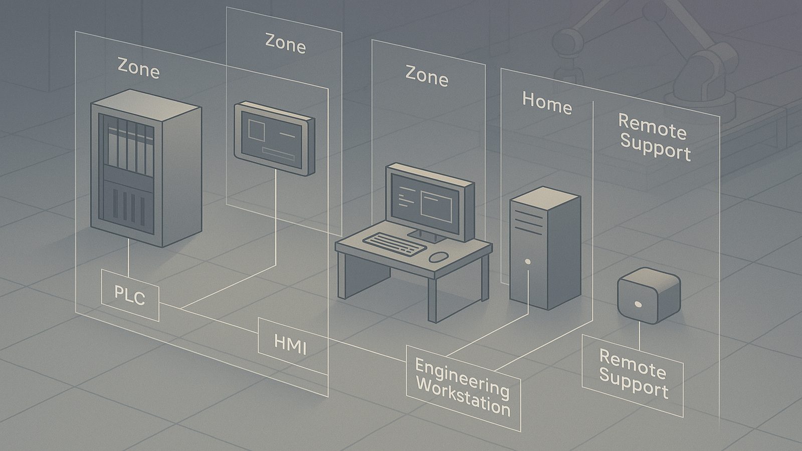
IEC 62443-3-2 is one of the most useful parts of the IEC 62443 series when you need to turn an OT security conversation into an engineering decision. It is the point where you stop talking in generalities about industrial cyber risk and start deciding which assets belong together, which communications are acceptable, and what level of protection each part of the environment actually needs.
For many UK SMEs, that sounds more formal than the reality on the ground. The plant may be small, the team may be lean, and the control environment may include a mix of modern PLCs, older HMIs, vendor laptops, and a historian that has been in place for years. In that setting, a worked example is often more valuable than a theoretical explanation. It shows how the assessment drives segmentation, access control, and monitoring choices that can be implemented without redesigning the whole site.
This article focuses on the practical side of zone and conduit modelling under IEC 62443, but with the emphasis on the risk assessment step that sits behind the model. If you already understand the basics of IEC 62443, the aim here is to show how to apply them in a way that is repeatable and defensible.
Key takeaways
- Start with the process and the trust boundaries, then let the zone model follow the risk rather than the other way round.
- Keep zones function-based and risk-based, not organisational, so that assets with different exposure and change profiles are not grouped together unnecessarily.
- Treat conduits as controlled communication paths with explicit rules, logging, and access conditions, especially for remote support.
- Use the assessment to create an implementation backlog, not just a diagram, and review it after plant or supplier changes.
Why IEC 62443-3-2 matters in practice
IEC 62443-3-2 is about defining the system under consideration, identifying risk, and using that risk to derive zone and conduit requirements. In plain terms, it helps you answer three questions: what are we protecting, what could go wrong, and how should the environment be divided so that the most important functions are not exposed to unnecessary risk?
That matters because OT environments are not designed like office IT. Availability is often more important than rapid change. Legacy protocols may not support strong authentication. Some equipment cannot be patched frequently. And remote support, if it exists, is often a business requirement rather than a convenience. A useful assessment therefore has to reflect operational reality, not just ideal security architecture.
It also helps avoid a common mistake: drawing zones first and then trying to justify them afterwards. The better approach is to start with process and risk, then let the zone model follow. That is the same risk-led logic used in risk assessment and treatment under ISO 27001, although the OT context adds constraints around safety, uptime, and physical process continuity.
Starting point: define the industrial scope and assumptions
Begin by deciding what is in scope. For a small manufacturing site, that might be one production line, one packaging cell, or one workshop with a handful of machines. Do not start with the whole company unless that is genuinely the right boundary. The scope should be specific enough to model, but broad enough to include the systems that influence the process.
In a first pass, capture the following:
- The process being supported, such as mixing, filling, packaging, or material handling.
- The business objective of the process, such as throughput, quality, traceability, or safety.
- The key assumptions, such as 24/7 operation, limited maintenance windows, or reliance on vendor support.
- The main constraints, including legacy equipment, safety interlocks, and any regulatory or contractual obligations.
For example, assume a UK food manufacturer runs one packaging line with a PLC controlling conveyors, a local HMI for operators, an engineering workstation used by maintenance staff, a historian collecting production data, and a remote support path used by the machine supplier. The line must keep running during business hours, and any security change that risks downtime needs careful scheduling.
At this stage, write down what is out of scope too. If the corporate office network, cloud ERP, or other plant lines are not part of the assessment, say so. Clear boundaries reduce confusion later when you decide where a zone begins and ends.
Build a usable asset and communication inventory
The next step is to identify the assets that actually matter to the process. A useful inventory is not a procurement list. It is a map of the components that exchange data, make control decisions, or provide access to those functions.
For the example line, the inventory might include:
- PLC controlling the packaging sequence.
- Safety controller or safety relay, if present.
- Operator HMI on the line.
- Engineering workstation used for configuration and diagnostics.
- Historian or local data collector.
- Industrial switch or switches connecting the cell.
- Remote access appliance, jump host, or vendor VPN endpoint.
- Any interface to MES, ERP, or quality systems.
Then map the communications. Note which systems talk to each other, what protocol they use, and whether the traffic is periodic, event-driven, or ad hoc. For OT, protocol detail matters because it often determines what can be inspected, filtered, or authenticated. If you need a broader view of protocol-specific monitoring, the article on monitoring OT protocols such as Modbus and DNP3 for anomalies is a useful companion piece, even if your environment uses a different protocol family.
A simple communication table might look like this:
- HMI to PLC: control and status updates on the local cell network.
- Engineering workstation to PLC: configuration, diagnostics, and firmware maintenance.
- PLC to historian: production counts and alarms.
- Remote vendor access to engineering workstation: support sessions during maintenance windows.
- Historian to MES or reporting platform: batch or scheduled data transfer.
Do not overcomplicate the first version. The goal is to identify trust relationships and dependencies, not to model every packet.
Group assets into zones based on risk and function
Once you understand the process and the communications, group assets into zones. A zone is a set of assets that share similar security requirements and trust assumptions. The grouping should be based on function, impact, and exposure, not on who owns the equipment or which department manages it.
For the example packaging line, a sensible first cut might be:
- Safety zone: safety controller, safety relays, and any components directly tied to safe shutdown.
- Control zone: PLCs and the devices that directly control the process.
- Supervisory zone: HMI, historian, and engineering workstation if it is used for line support.
- Remote access zone: jump host or remote support appliance used by internal staff or vendors.
- Enterprise interface zone: interface to MES, reporting, or other business systems.
This is where many teams benefit from comparing the model with the Purdue structure. The Purdue model is not a standard in itself, but it remains a practical reference for thinking about industrial layering. If you want to see how that layering maps to IEC 62443 zones, the article on segmenting OT networks with the Purdue model and IEC 62443 zones gives a useful architectural view.
When grouping assets, use consistent criteria. For example, place systems together only if they have similar availability requirements, similar trust levels, and similar exposure to change. Do not put the historian in the same zone as the PLC just because they sit in the same cabinet. The historian is usually more exposed, more changeable, and more likely to need connectivity beyond the cell.
Define conduits and the controls that sit between zones
Conduits are the communication paths between zones. Once the zones are defined, the next question is which paths are allowed, under what conditions, and with what controls. This is where the risk assessment becomes operational.
For each conduit, decide:
- Whether the communication is necessary.
- Which direction the traffic should flow.
- Whether the path is permanent or only enabled for maintenance.
- What inspection, authentication, or logging is required.
Typical controls include industrial firewalls, jump hosts, protocol-aware inspection, one-way transfer mechanisms where appropriate, and tightly controlled remote access. In some cases, network address translation or port restrictions may be enough. In others, you may need application-layer filtering or a dedicated remote support workflow.
For the example line, the conduit between the remote access zone and the supervisory zone might require a jump host, MFA for the remote user, session logging, and time-bound approval. The conduit between the control zone and the enterprise interface zone might allow only historian traffic on specific ports, with no direct access from the corporate network to the PLCs.
Keep the control choice proportional to the risk. A small site does not need a complex architecture if a simpler design achieves the same outcome. The point is to reduce unnecessary trust, not to create a maze of devices that nobody can maintain.
Work through a simple zone partitioning example
Here is a worked example for a small manufacturing environment. Assume the site has one production cell with a PLC, an HMI, an engineering workstation, a historian, and a vendor support path.
First, identify the highest-value functions. In this case, the PLC and safety functions are critical because they control the process and protect people and equipment. The HMI is important because operators need visibility and control. The engineering workstation is powerful because it can change logic, recipes, and configuration. The historian is important for traceability, but it does not need the same level of trust as the PLC.
Now assign zones:
- Zone 1, safety: safety controller and related safety components.
- Zone 2, control: PLC and any tightly coupled control devices.
- Zone 3, operations: HMI and operator-facing support systems.
- Zone 4, engineering: engineering workstation, but only if it is not used for general office work.
- Zone 5, data exchange: historian and any interface to business systems.
- Zone 6, remote support: vendor access path, isolated from direct plant control.
Then define the conduits:
- Operations to control: HMI to PLC, limited to required control and status traffic.
- Engineering to control: maintenance access, enabled only when needed and logged.
- Control to data exchange: historian collection, restricted to specific data flows.
- Remote support to engineering: vendor access via jump host, not direct access to the PLC.
This model is not perfect, but it is usable. It gives you a basis for firewall rules, remote access design, and monitoring priorities. It also makes it easier to explain to operations staff why some connections are allowed and others are not.
If remote support is required, the model should change rather than be ignored. A vendor VPN that lands directly on the engineering workstation is usually too much trust. A better pattern is a dedicated remote access zone with a jump host, session recording, and explicit approval for access windows. That reduces the blast radius if credentials are misused or a vendor account is compromised.
Assess threats, impact, and likelihood for each zone
IEC 62443-3-2 expects you to consider risk in a structured way. You do not need a heavyweight quantitative model to make progress. A repeatable qualitative method is often enough, provided it is documented and applied consistently.
For each zone and conduit, consider the main threat scenarios. In a small OT environment, the most common practical scenarios are:
- Unauthorised access through remote support or weak credentials.
- Malware spreading from IT into OT through shared systems or removable media.
- Misconfiguration or accidental change by an authorised user.
- Loss of availability caused by a network fault, patching issue, or overloaded device.
- Process disruption caused by unauthorised logic changes or command injection into control traffic.
Score impact and likelihood in a simple matrix. For example, unauthorised access to the engineering workstation may have high impact because it can alter PLC logic, but the likelihood may depend on whether the workstation is isolated, whether MFA is used, and whether vendor access is tightly controlled. Malware spread from the office network may be less likely if the OT environment is segmented, but the impact could still be high if a shared file server or USB workflow bridges the gap.
The important point is not the exact score. It is the reasoning behind it. If the team can explain why a conduit is high risk, the control decision becomes much easier to justify and maintain.
Set security level targets and justify them
Security level targets translate the risk assessment into an expected level of resilience for each zone or conduit. They should reflect the consequences of compromise, the exposure of the asset, and the practical ability to implement controls.
In a small plant, you may decide that the control zone needs a higher target than the data exchange zone because compromise of the PLC would directly affect production and possibly safety. The engineering zone may also need a high target because it can change the behaviour of the process. The historian may need a lower target than the control zone, but still enough protection to prevent it becoming a pivot point.
Where you cannot meet the target immediately, record the gap and the compensating controls. For example, if an older PLC cannot support strong authentication, you may compensate with strict network isolation, limited access paths, and enhanced monitoring. That is not the same as eliminating the risk, but it is a practical way to reduce exposure while planning a longer-term replacement.
This is also where it helps to align the assessment with a broader architecture method. A risk-driven structure such as SABSA framework for risk-driven security architecture can help you keep the business objective, risk, and control design connected, rather than treating the OT model as a standalone diagram.
Turn the assessment into an implementation backlog
A good assessment should produce work, not just documentation. Convert the findings into an implementation backlog with owners, priorities, and dependencies.
Useful backlog items might include:
- Separate the engineering workstation from general office use.
- Place the historian in its own zone with tightly scoped data flows.
- Introduce a jump host for vendor support.
- Restrict PLC access to approved management stations only.
- Enable logging on firewalls and remote access devices.
- Review protocol exposure and remove unused services.
- Document maintenance windows and access approval steps.
Sequence the work sensibly. Quick wins often include access control changes, firewall rule tightening, and remote access redesign. Longer-term work may involve replacing legacy devices, redesigning the cell network, or introducing protocol-aware inspection. If you need to justify the effort, frame it in terms of reduced downtime risk, easier troubleshooting, and lower chance of accidental change.
Validate the design and keep it current
Zone models go stale quickly if they are not maintained. A new vendor, a line upgrade, a temporary bypass, or a change in data flow can invalidate the original assumptions. That is why validation matters as much as the initial design.
Check the model against reality by asking a few simple questions:
- Do the documented zones still match the live network?
- Are there any direct connections that bypass the intended conduits?
- Has remote access changed since the last review?
- Have any new assets been added without being classified?
- Are logs and alerts available for the most important conduits?
Review the assessment after plant changes, supplier changes, incidents, or significant maintenance work. Even a small change, such as a new remote support tool, can alter the trust model enough to require a fresh look. The best OT security teams treat the zone diagram as a living engineering artefact, not a one-off deliverable.
Common mistakes to avoid
The most common mistake is creating zones that are too broad. If a zone contains assets with very different trust levels, the weakest asset tends to set the standard for the whole group. That makes the zone less useful and can hide risk.
The second mistake is treating the diagram as the end of the exercise. A neat drawing is not a control. The value comes from the rules, restrictions, and monitoring that follow from it.
Other mistakes include:
- Ignoring vendor access because it is inconvenient to model.
- Allowing direct office-to-PLC connectivity for convenience.
- Assuming older equipment can be protected by patching alone.
- Failing to document why a conduit exists.
- Not revisiting the model after operational changes.
These are avoidable issues if the assessment is run as a practical engineering exercise rather than a paperwork task.
For teams that are still building their OT security baseline, it can also help to compare the model with broader organisational risk work, such as the approach described in defining and documenting risk appetite. The language is different, but the discipline of making risk decisions explicit is the same.
In summary, IEC 62443-3-2 is most valuable when it helps you make concrete decisions about segmentation, access, and monitoring. A good worked example starts with the process, identifies the assets and flows that matter, groups them into sensible zones, and then defines conduits and controls that reflect real operational constraints. If you can explain why each zone exists and what risk it is designed to contain, you are already doing the standard the way it was intended.
If you would like help turning an OT risk assessment into a practical segmentation plan, Speak to a consultant.
Frequently asked questions
How is IEC 62443-3-2 different from zone and conduit modelling?
IEC 62443-3-2 is the risk assessment step that informs the model. Zone and conduit modelling is the architectural output, while 3-2 helps you decide how to partition the environment and what controls each path needs.
What should a small team include in a first-pass zone partitioning exercise?
Include the process scope, key assets, communication flows, remote access paths, safety dependencies, and the main constraints such as uptime, legacy equipment, and maintenance windows. That is usually enough to produce a useful first model.
Comments are closed